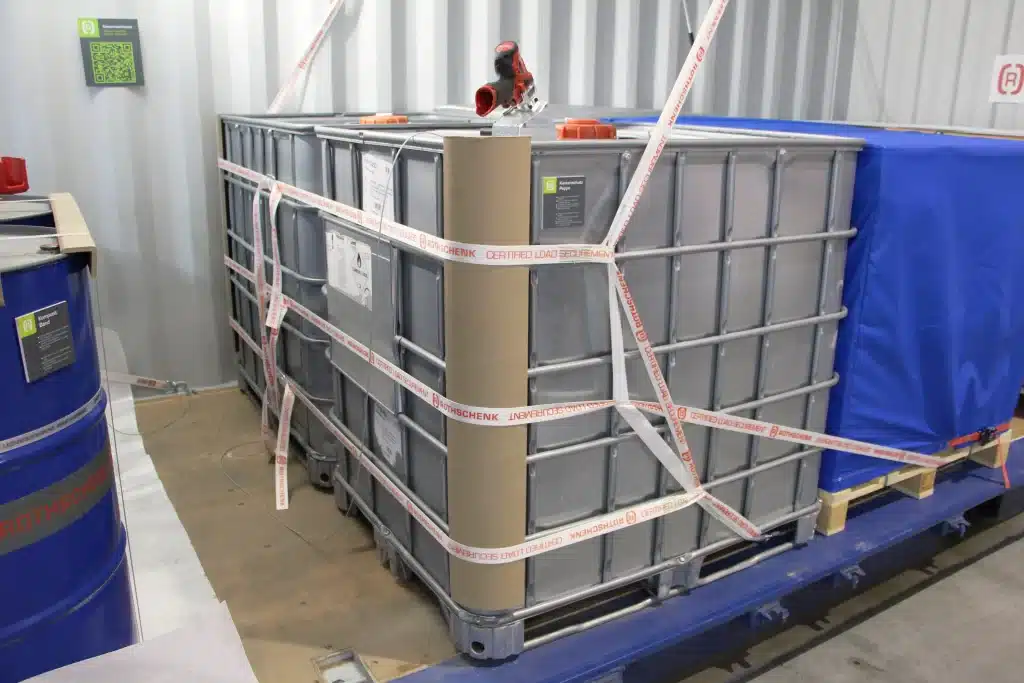
Now 10% off all Ergolash lashing straps save now! Voucher code: ergo10 | Valid until 31.05.2025
Stowing a container does not begin when it is standing in the yard with the rear doors open, but when it is clear that a container is required.
Those involved or affected are not only those who load the container, but also those who develop, design and plan the production of the goods or merchandise in order to have them transported by container.
The usual Euro size, represented by the Euro pallet 120 x 80 cm, as well as divisions/multiples, does not fit into the container. Its dimensions are based on the American foot measure.
The CP3 pallet with 114 x 114 cm would be better suited for this. It therefore makes sense to consider the dimensions in advance so that no complex securing measures are required in the container afterwards.

The standard 20ft container has internal dimensions of L x W x H = 5.919 x 2.34 x 2.376 m, although the door dimensions differ. Their width is 2.286 m and the height is 2.277 m. If the load or load carrier is manufactured to fit precisely, this deviation must be taken into account.
The design of machines and systems in particular requires special care. If the system exceeds the container dimensions and is not to be transported as a whole, then the dismantling capability must also be designed.
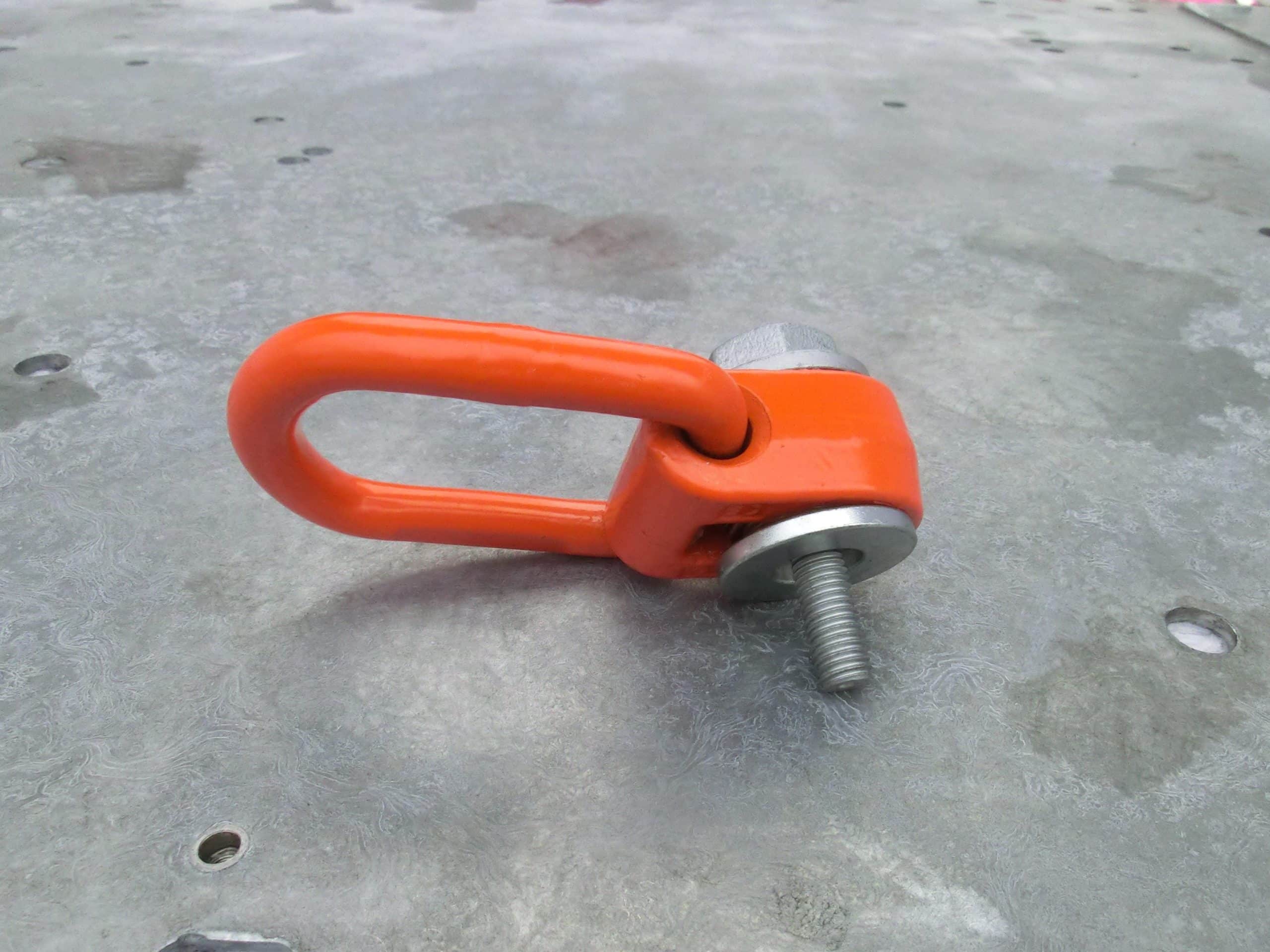
As it is often not possible to stow systems in a form-fit manner, it is also necessary to check at which points it makes sense to attach attachment points in order to secure them by direct lashing.
Bolt-on lashing points would be a good approach here, because threaded holes are often already present on the machines/equipment for other applications and can be used for the attachment points.
However, the design must confirm their load-bearing capacity.

The following sketches are not to scale because they are only intended to illustrate the thought processes. The scale is absolutely essential for practical use.
A simple solution is to create a scaled floor plan of the container floor area. The dimensions of the load units can be entered on it and it is easier to see whether and how they fit.
The diagram shows the classic block of five Euro pallets and the gap that inevitably results from the dimensions. You can now consider how the gap should be closed. The elegant methods are dunnage bagThe other is to use empty pallets or the elaborate method of palletizing with wood.

In the following congestion plan, three points can be recognized without calculating:
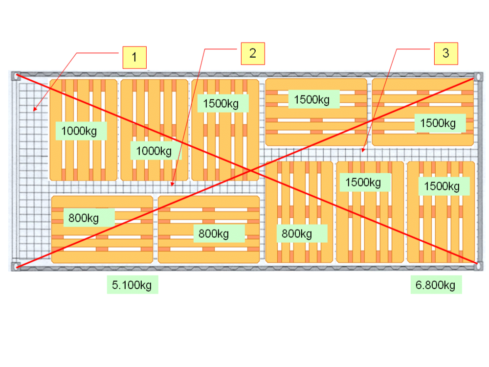
By adding up the individual weights, the imbalance can be seen even more clearly.
The above finding leads to the following measures:

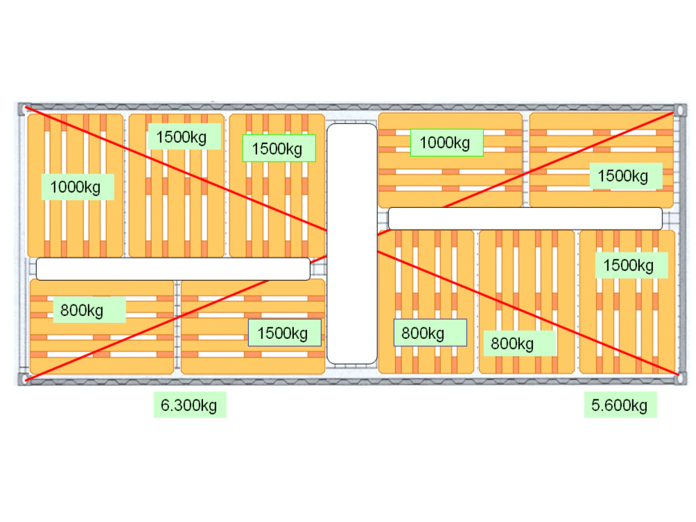

Sometimes the height of the components cannot be reduced far enough by design and the internal container height is exceeded. It is now necessary to use an Opentop container of type 22U1 or 42U1 with tarpaulin cover. This results in two further measures:
Some machines or systems stand on feet that are quite small or can be adjusted using screws. As a result, the weight is often distributed over very small areas.
It must be taken into account that the maximum load on the container floor is limited to 5,460 kg (axle load when using a forklift truck). Converting with the wheel contact area gives a value of 19 kg/cm2.
It is therefore necessary to calculate the surface load of the machine/installation and if the result is greater than 19 kg/cm2, plates/wood or similar must be placed under the feet.
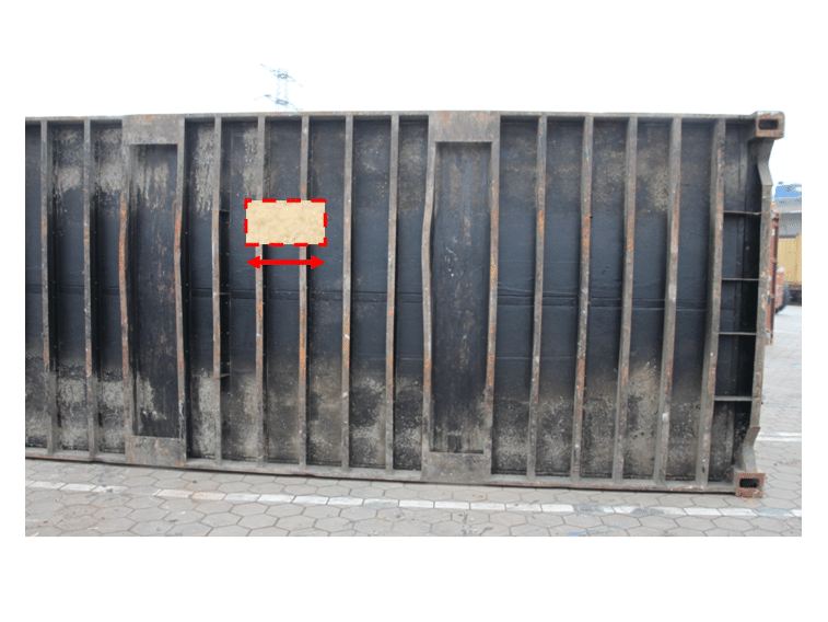
The picture shows the floor construction of a container with the cross beams, which are partially bent. The thickness of the floor panels in the gaps is only 26-28 mm.
The substructure for machines/equipment should be large enough to bridge at least two cross beams.

The rows of bolts in the container floor make it easy to locate the floor cross members.
If possible, the contact area enlargement should always overlap at least two cross beams.

This picture shows damage caused by an excessive point load.
The topic of congestion planning is far from over and will be continued in one of the next episodes. The above ideas should be used to check how things work in practice in your own company.
Perhaps one or two people will notice something when they look at the processes through the new glasses.
Yours, Sigurd Ehringer
<< Previous post
Episode 10: Force closure
Next post >>
Episode 12: How does a anti-slip mat work?

Sigurd Ehringer
✔ VDI-zertifizierter Ausbilder für Ladungssicherung ✔ Fachbuch-Autor ✔ 8 Jahre Projektmanager ✔ 12 Jahre bei der Bundeswehr (Kompaniechef) ✔ 20 Jahre Vertriebserfahrung ✔ seit 1996 Berater/Ausbilder in der Logistik ✔ 44 Jahre Ausbilder/Trainer in verschiedenen Bereichen —> In einer Reihe von Fachbeiträgen aus der Praxis, zu Themen rund um den Container und LKW, erhalten Sie Profiwissen aus erster Hand. Wie sichert man Ladung korrekt und was sind die Grundlagen der Ladungssicherung? Erarbeitet und vorgestellt werden sie von Sigurd Ehringer, Inhaber von SE-LogCon.
Rothschenk assortment
Our customer center has only one goal: to turn your problems into solutions. Whether standard stowage cushions, bestsellers or load securing personally tailored to your needs -. we accompany you consistently from A as in field service to Z as in certification. That is our promise to you, as a leader in our industry.
We attach great importance to professional cargo securing. That is why we have our own production, which ensures reliable operation through modern manufacturing technologies and strict quality control. Thus, we offer our customers a comprehensive and high-quality range of services in the field of transport logistics.
DIN ISO 9001:2015, EMAS and Ecovadis are not foreign words to you? Then it's time to work with the best.
You don't take any risks with us - we have been awarded the Platinum Medal on the EcoVadis sustainability rating platform.
As a load securement company, we are proud to have several certifications that validate our sustainability efforts and our commitment to environmental protection and social responsibility. For you as a purchaser, this means that we demand and promote the implementation of high environmental and social standards both within the company and along the supply chain.
You are currently viewing a placeholder content from Google Maps. To access the actual content, click the button below. Please note that doing so will share data with third-party providers.
More Information