
Now 10% off all Ergolash lashing straps save now! Voucher code: ergo10 | Valid until 31.05.2025
Load distribution on trucks is a constant challenge for both drivers and loaders, which is often approached with “half-knowledge”.
Provided you have some basic knowledge of physics, the problem can be solved quite easily.
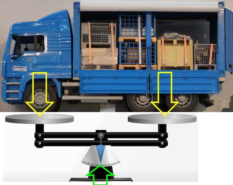
The simplest approach is to imagine that the truck is standing with its axles on a scale.
If the load distribution is correct, the pointer of the scale is at zero or centered.
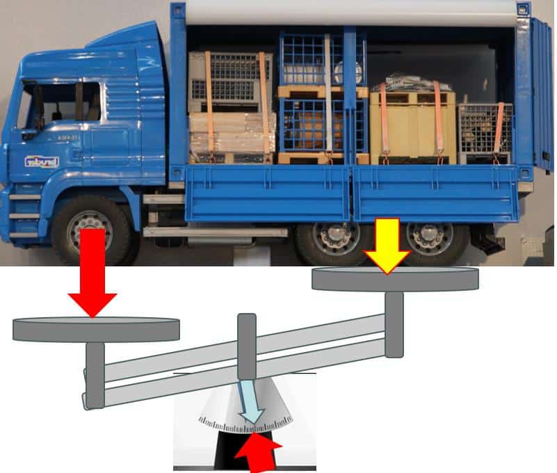
If the front axle were overloaded, the left-hand pan would lower and the right-hand pan would raise. That would be the clear result of incorrect load distribution.
The whole thing would of course be reversed if the rear axle were overloaded.
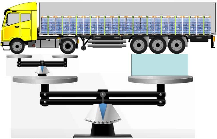
This basic principle applied to a semi-trailer can be simplified by adding another scale to the left-hand weighing pan, on which the steering and drive axles rest.

The “DGUV70 Fahrzeuge” rules and regulations of the German Social Accident Insurance Institution (DGUV) state the following boundary conditions in the commentary:
To § 37 Para. 1: The requirement for compliance with the permissible values for the axle loads is met if:
If the driving speed does not exceed 25 km/h, the minimum axle load of the steered axle may be reduced to 10% of the vehicle torque weight.
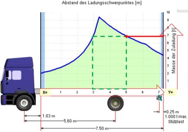
The main basis for the considerations is the load distribution plan, which is specific to each vehicle type. The template for the image is a BG program for calculating load distribution plans. The image has been modified for illustration purposes.(Load distribution plan LVP 4.1 + Basic principles of load securing – BG Verkehr (bg-verkehr.de))

The total center of gravity of the load must always be below the blue line. A charge with max. 2,000 kg, can be positioned anywhere on the loading area. However, if the load weighs 9,000 kg, the center of gravity must be at a distance of 3.40 m from the bulkhead. The heavier the load, the smaller the clearance.
Two graphical axes are also important in the chart. The X-axis indicates the length of the loading area and the Y-axis the payload.
Example: If the whole load weighs 7,000kg, then go to Y=7to and then to the left to the blue line.
It is intersected twice, so the center of gravity of the load can be at a distance of 3m to 5m from the end wall.
However, there is another way to determine the center of gravity. You have to remember the law of leverage . The force (load weight) multiplied by the length of the lever (distance from the end wall to the center of gravity of the load unit) results in a moment. A torque wrench works on the same principle. In this case, however, the lever length remains the same and the force can be adjusted.
When using this method, it is necessary to know the position of the center of gravity on the load. In the case of machines and systems in particular, the design department often fails to mark the position of the center of gravity or at least to provide a drawing showing its position. This information is crucial for correct loading and load securing.
The following is a fictitious example of how the center of gravity can be determined for similar load units.


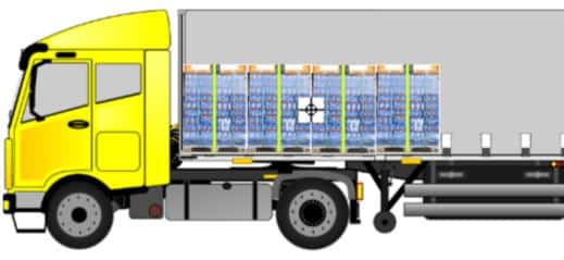

With similar loads, such as big bags, octabins, IBCs or beverage pallets, the center of gravity moves further back with each row of loading. The exact weight does not necessarily have to be known for this consideration.
At the end of loading, the driver and the loader must know whether the position of the overall center of gravity (green arrow) is permissible or not. If this position were not permitted, the cargo would have to be reloaded, unloaded and restowed.
Of course, the problem can also be solved mathematically. It is not difficult, but it is hard work.
Take the weight (in kg) of the first load and multiply it by the distance (in m) between the center of gravity and the front wall. If the load units are of the same type, the entire load series can also be used.
The second load, multiplied by the new center of gravity distance, is then added to the first result and so on until all load units have been calculated.
The summed result is divided by the total weight of the load.
The result is the distance between the total center of gravity of the load and the front wall.
For a standard semi-trailer with maximum payload, this distance must be between 6.80 and 7.2.


Those of our readers who are reasonably fit with Excel can make the calculation work easier for themselves. You create a table that provides you with the result after entering the data.
With this basic knowledge, it should be possible to stow the loads correctly to such an extent that an infringement of operational and traffic safety is avoided.
It must always be borne in mind that, in addition to an administrative offense, this could also result in a criminal offense. Namely, if an incorrectly loaded vehicle results in an accident with injuries, fatalities or major material damage.
We all want to avoid this, because as road users we can also be affected at any time.
Yours, Sigurd Ehringer
<< Previous article
Episode 36: Code XL – Loading the front wall – What needs to be considered?
To the next post >>
Episode 38: How does an anti-slip mat work? – Part 1: The principle of action

Sigurd Ehringer
✔ VDI-zertifizierter Ausbilder für Ladungssicherung ✔ Fachbuch-Autor ✔ 8 Jahre Projektmanager ✔ 12 Jahre bei der Bundeswehr (Kompaniechef) ✔ 20 Jahre Vertriebserfahrung ✔ seit 1996 Berater/Ausbilder in der Logistik ✔ 44 Jahre Ausbilder/Trainer in verschiedenen Bereichen —> In einer Reihe von Fachbeiträgen aus der Praxis, zu Themen rund um den Container und LKW, erhalten Sie Profiwissen aus erster Hand. Wie sichert man Ladung korrekt und was sind die Grundlagen der Ladungssicherung? Erarbeitet und vorgestellt werden sie von Sigurd Ehringer, Inhaber von SE-LogCon.
Rothschenk assortment
Our customer center has only one goal: to turn your problems into solutions. Whether standard stowage cushions, bestsellers or load securing personally tailored to your needs -. we accompany you consistently from A as in field service to Z as in certification. That is our promise to you, as a leader in our industry.
We attach great importance to professional cargo securing. That is why we have our own production, which ensures reliable operation through modern manufacturing technologies and strict quality control. Thus, we offer our customers a comprehensive and high-quality range of services in the field of transport logistics.
DIN ISO 9001:2015, EMAS and Ecovadis are not foreign words to you? Then it's time to work with the best.
You don't take any risks with us - we have been awarded the Platinum Medal on the EcoVadis sustainability rating platform.
As a load securement company, we are proud to have several certifications that validate our sustainability efforts and our commitment to environmental protection and social responsibility. For you as a purchaser, this means that we demand and promote the implementation of high environmental and social standards both within the company and along the supply chain.
You are currently viewing a placeholder content from Google Maps. To access the actual content, click the button below. Please note that doing so will share data with third-party providers.
More Information