Now 10% off all Ergolash lashing straps save now! Voucher code: ergo10 | Valid until 31.05.2025
In some load securing situations, wedges are a perfectly viable solution. Especially round loads such as pipes, poles, masts and, of course, wheels. However, there is often a lack of knowledge about which wedge shapes are available, which regulations apply and how they should be applied. Most mistakes are made when cutting wooden wedges in particular.
An important source is VDI-2700 09-2004 “Load securing on road vehicles”. Goods in roll form are described there in chapter 3.3.
This is what I would like to address in today’s blog.

There are basically two variants of wedge profiles:
They differ in the wedge angle in relation to the grain direction of the wood.
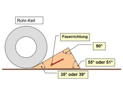

With the pipe wedge, the longitudinal direction of the wood fibers runs along the side of the load. With box wedges, the longitudinal direction of the wood fiber runs on the opposite side of the load.
The operating principle of this securing method is called “positive locking” of a round or square profile against horizontal movement. The running direction of the fibers is important because the nails must always be attached at right angles to them. This is where the box wedge and pipe wedge differ.
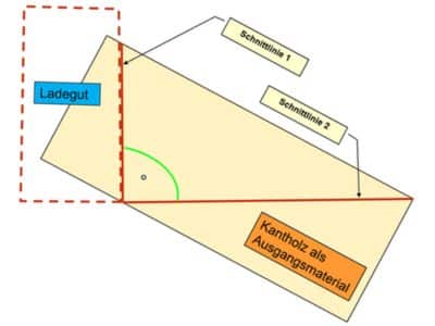
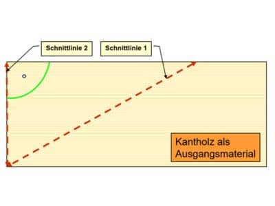
The first picture shows the diagram with the cutting lines for the saw when making a box wedge from a beam.
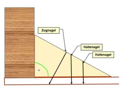
First, the load must be placed on a nailable loading surface made of softwood.
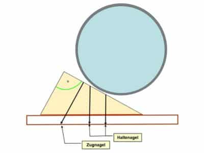
Then the towing pin is placed first. It ensures the flush, form-fit positioning of the wedge. Only then are the retaining nails placed.
The depth at which the nails are driven into the loading surface must be 8 times the nail diameter or at least 40 mm in order to develop the necessary retaining force.
The nail length must therefore be selected accordingly.
With pneumatic nailers, it must be checked whether the nails actually penetrate the base and do not just get stuck in the wedge.
The picture shows the diagram with the cutting lines for the saw when producing a pipe wedge from a squared timber profile.
The most common cause of false wedges is that the fence on the circular saw is set to 45° and the beam is rotated with each cut. This means that there is no waste, but also no roll or box wedge.

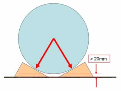
In contrast to the box wedge, the pairs of pipe wedges must first be placed and nailed. The distance between the wedges depends on the diameter of the load and must be measured/calculated beforehand. The load can only be stowed once the wedges have been nailed.
It is ideal if the load touches the wedges as a point load because it is then optimally held. The distance between the lowest point of the load and the loading surface should be at least 20 mm.
A common mistake is to reverse the order. First the load is stowed and then the wedges are placed. This creates an unstable three-point support that allows the load to move during transportation. Because the wedges are nailed from the outside, they can come loose during these rolling movements and the securing effect is lost.


Practical example
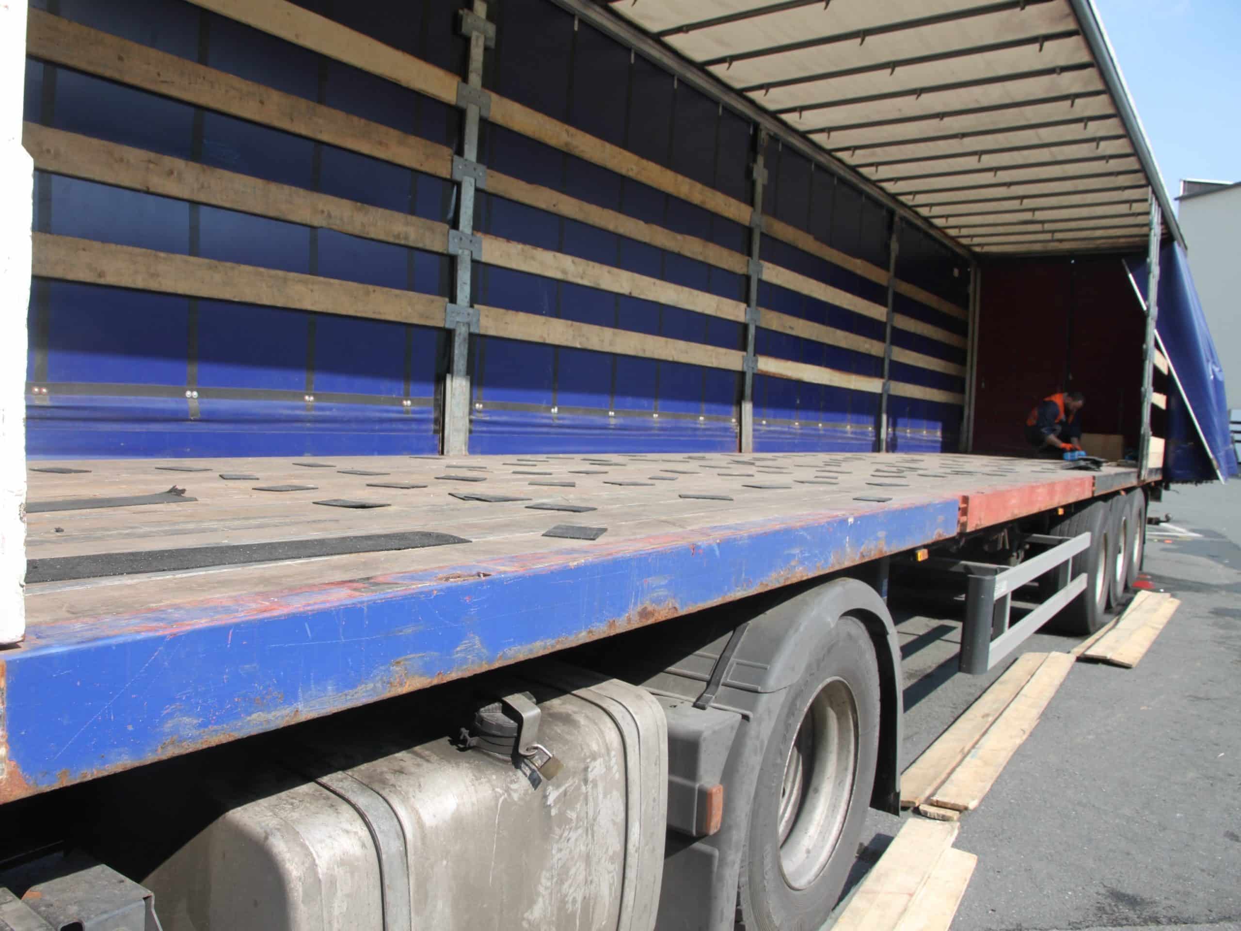
The three-point support is clearly visible in this picture. The wedges are also cut incorrectly because the angles are not correct.
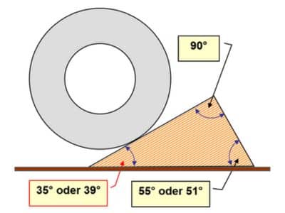
If the rolling direction is also the direction of travel during loading, the wedge angle on the load side must be at least 39°. If loading across the direction of travel, it must be at least 35°.
This automatically results in counter angles of 55° or 51°
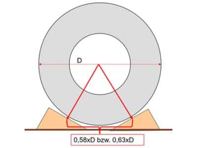
The distance between the support points must be 0.63xD in the direction of travel and 0.53xD at right angles to it.
Further details on the distances can be found in Table 2 in Chapter 3.3 of VDI-2700.

Attention
When trimming, no attention is paid to the grain direction, which means that the end grain side always becomes the nail side.
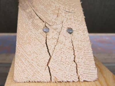


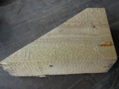
Image 1: Because the wedges are cut incorrectly, the nails are hammered into the end grain. A dry wedge jumps immediately, a wet one when it dries. The securing force is therefore no longer provided.
It can break apart completely under longitudinal loads.
Fig. 2: Nails must be long enough to achieve the nail depth of 40 mm.
Figure 3: In this example, the three nails were driven in with the pneumatic nailer.
Figure 4: This is the underside of the same wedge. None of the nails went through the wedge because they are too short. This is a disadvantage of the pneumatic nailer because the same nail length is always in the magazine and cannot be changed.
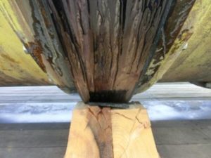
Practical example
This picture clearly shows that the incorrectly cut wedge has already been damaged by the load.
The above information is intended to encourage the reader to check the wedges used in their own area. It is not uncommon for wedges to be purchased from a supplier who does not have the necessary expertise. In order to avoid unpleasant consequences, it should be clarified with the supplier according to which regulations he manufactures the wedges. It can be fatal to rely on the fact that he will cut the wedges correctly.
An interesting source with negative examples and the resulting consequences are the following links:
As a caller in the load securing desert, I hope that one or two people will hear me.
Yours, Sigurd Ehringer

Sigurd Ehringer
✔ VDI-zertifizierter Ausbilder für Ladungssicherung ✔ Fachbuch-Autor ✔ 8 Jahre Projektmanager ✔ 12 Jahre bei der Bundeswehr (Kompaniechef) ✔ 20 Jahre Vertriebserfahrung ✔ seit 1996 Berater/Ausbilder in der Logistik ✔ 44 Jahre Ausbilder/Trainer in verschiedenen Bereichen —> In einer Reihe von Fachbeiträgen aus der Praxis, zu Themen rund um den Container und LKW, erhalten Sie Profiwissen aus erster Hand. Wie sichert man Ladung korrekt und was sind die Grundlagen der Ladungssicherung? Erarbeitet und vorgestellt werden sie von Sigurd Ehringer, Inhaber von SE-LogCon.
Rothschenk assortment
Our customer center has only one goal: to turn your problems into solutions. Whether standard stowage cushions, bestsellers or load securing personally tailored to your needs -. we accompany you consistently from A as in field service to Z as in certification. That is our promise to you, as a leader in our industry.
We attach great importance to professional cargo securing. That is why we have our own production, which ensures reliable operation through modern manufacturing technologies and strict quality control. Thus, we offer our customers a comprehensive and high-quality range of services in the field of transport logistics.
DIN ISO 9001:2015, EMAS and Ecovadis are not foreign words to you? Then it's time to work with the best.
You don't take any risks with us - we have been awarded the Platinum Medal on the EcoVadis sustainability rating platform.
As a load securement company, we are proud to have several certifications that validate our sustainability efforts and our commitment to environmental protection and social responsibility. For you as a purchaser, this means that we demand and promote the implementation of high environmental and social standards both within the company and along the supply chain.
You are currently viewing a placeholder content from Google Maps. To access the actual content, click the button below. Please note that doing so will share data with third-party providers.
More Information