Now 10% off all Ergolash lashing straps save now! Voucher code: ergo10 | Valid until 31.05.2025
Cargo must be secured in the container.
It is not a question of “whether to secure”, but rather “how to secure a load”. Even experts do not always agree on the “how”. Some say: “nothing has ever happened” and others: “it can’t work like that”.
One of many securing methods is the use of dunnage bags. Some of you may be familiar with these air bags that fill the empty spaces in parcels and packages and prevent the contents from moving. This is based on the same principle as the container.

The regulations for securing loads in containers are set out in the CTU Code 2015. In Appendix 7, Annex 4, an entire chapter is devoted to the securing method with dunnage bags.
It states that dunnage bag should “block” the movement of the load. Conversely, this means that it is a positive locking method.

Three pieces of information are required to determine the size of the stowage cushion:
In principle, a distinction can be made between two types.


The main objective must always be to prevent cargo movement. This means that the force generated by the movement of the charge is compensated with the dunnage bag to compensate for it.
In principle, the considerations can be approached from different angles:
In practice, in my experience, the third variant is most frequently used.

For example, the classic block of five in a container. There are two options here. Either one large cushion or two small ones.
The large one is useful if the load is essentially always the same.
The little ones are more versatile. The pad size and force absorption can be precisely determined by the height of the load unit.

It is also important to know the relationship between pressure and surface area.
The greater the pressure and the smaller the area, the greater the acting force. This connection is the most frequent cause of faults or damage.

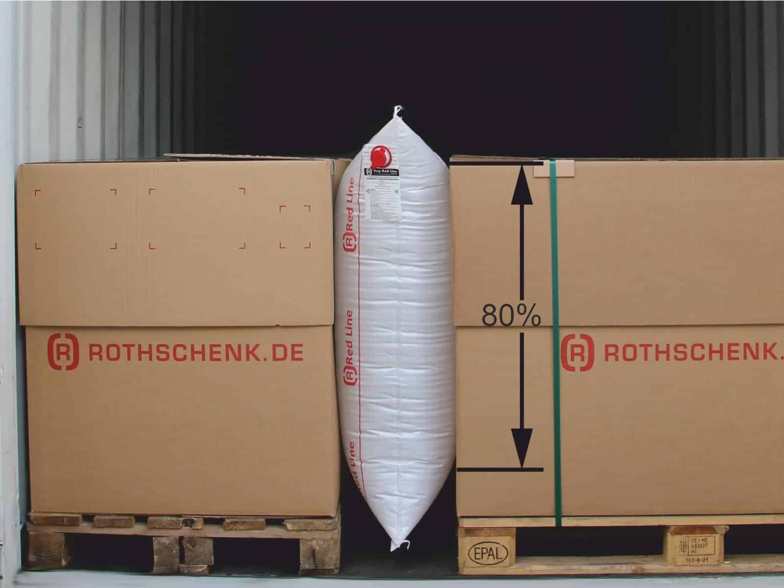
The aim should be for approx. 80% of the dunnage bag surface to be in contact with the load, as this enables optimum force transmission/force absorption.
Situations such as the example below pose a considerable risk to the functionality of the traffic jam cushion. In the event of an inspection, the container would first be shut down and improvements would have to be made. This is usually time-consuming and cost-intensive.


The CTU Code describes the topic very comprehensively and theoretically. Many shippers are overwhelmed because all the formulas look complicated, but on closer inspection they are not.
A distinction is made between loads that slide/slide and those that can tip because they are of different heights. Before solving the problem of loads of different heights with the stowage cushion calculation, it is often easier to compensate for the different heights, e.g. by using a pallet substructure.
Only simple solutions are effective in the long term.
Of course, it is important that no technical mistakes are made, such as positioning a dunnage bag where the container is damaged and the upholstery could be worn through.
It is important to note that in the following calculations according to the CTU Code, the cargo mass is given in tons (to).
The result is then converted into deca-Newtons (daN), because most shippers are more familiar with this.
Sliding:
FLADUNG = m * g * (cx,y – μstatic * 0.75 * cz ) [kN]
Tilting:
FLADUNG = m * g * (cx,y – bp /hp * cz ) [kN]
Below are a few excerpts from the CTU code with explanations.
The following formula calculates the force generated by a sliding/sliding load.
It should be noted that the coefficient of sliding friction µstatic is not known in most cases or is only estimated. It is therefore reduced by a factor of 0.75.
During sea transportation, the vertical acceleration Cz can be between 0.2 g and 1.8 g when the ship is pitching. So there are considerable differences.
The acceleration when rolling the ship can be up to 0.8 g. This corresponds to a roll angle of 38º. A rolling period of between 2-3 times per minute is not unusual.
Glide:
FLAG = m * g * (cx,y – μstatic * 0.75 * cz ) [kN]
FL= 1to * 9.81 m/s2 * (0.8 – 0.3 x 0.75 x 0.2 g)
FL = 9.81 kN * (0.8 – 0.045)
FL = 9.81 kN * 0.755 = 7.406 kN = 740.6 daN
FL = 1 to * 9.81 m/s2 * (0.8 – 0.3 * 0.75 * 1.0 g)
FL = 9.81 kN * (0.8 – 0.225)
FL = 9.81 kN * 0.575 = 5.641 kN = 564.1 daN
FL = 1 to * 9.81 m/s2 * (0.8 – 0.3 * 0.75 * 1.8 g)
FL = 9.81 kN * (0.8 – 0.405)
FL = 9.81 kN * 0.324 = 3.178 kN = 317.8 daN
In the worst case, with a vertical acceleration of only 0.2 g, the force from the load is more than twice as great as under normal circumstances. The load calculation should therefore be based on the first example.
When calculating the load force, taking into account the risk of tipping, the length/width(bp) of the package is set in relation to the height(hp). This results in the tilt factor. It increases the force generated by the load when tipping.
The figures on the right show the difference when a Euro pallet is positioned lengthways or crossways to the direction of acceleration under the same conditions.
A stowage plan helps to make it easier to assess the situation and decide how to stow.
Tipping:
FLAG = m * g * (cx,y – bp /hp * cz ) [kN]
FL = 1to * 9.81 m/s2 * (0.8 – 0.80 m/ 1.90 m * 1.0 g)
FL = 9.81 kN * (0.8 – 0.42)
FL = 9.81 kN * 0.38 = 3.728 kN = 372.8 daN
FL = 1 to * 9.81 m/s2 * (0.8 – 1.20 m/1.90 m x 1.0 g)
FL = 9.81 kN * (0.8 – 0.63)
FL = 9.81 kN * 0.17 = 1.668 kN = 166.8 daN
Yours, Sigurd Ehringer
<< Previous post
Episode 19: Combined transport
Next Post >>
Episode 21: dunnage bag Load securing – Part 2

Sigurd Ehringer
✔ VDI-zertifizierter Ausbilder für Ladungssicherung ✔ Fachbuch-Autor ✔ 8 Jahre Projektmanager ✔ 12 Jahre bei der Bundeswehr (Kompaniechef) ✔ 20 Jahre Vertriebserfahrung ✔ seit 1996 Berater/Ausbilder in der Logistik ✔ 44 Jahre Ausbilder/Trainer in verschiedenen Bereichen —> In einer Reihe von Fachbeiträgen aus der Praxis, zu Themen rund um den Container und LKW, erhalten Sie Profiwissen aus erster Hand. Wie sichert man Ladung korrekt und was sind die Grundlagen der Ladungssicherung? Erarbeitet und vorgestellt werden sie von Sigurd Ehringer, Inhaber von SE-LogCon.
Rothschenk assortment
Our customer center has only one goal: to turn your problems into solutions. Whether standard stowage cushions, bestsellers or load securing personally tailored to your needs -. we accompany you consistently from A as in field service to Z as in certification. That is our promise to you, as a leader in our industry.
We attach great importance to professional cargo securing. That is why we have our own production, which ensures reliable operation through modern manufacturing technologies and strict quality control. Thus, we offer our customers a comprehensive and high-quality range of services in the field of transport logistics.
DIN ISO 9001:2015, EMAS and Ecovadis are not foreign words to you? Then it's time to work with the best.
You don't take any risks with us - we have been awarded the Platinum Medal on the EcoVadis sustainability rating platform.
As a load securement company, we are proud to have several certifications that validate our sustainability efforts and our commitment to environmental protection and social responsibility. For you as a purchaser, this means that we demand and promote the implementation of high environmental and social standards both within the company and along the supply chain.
AUF ALLE
WHITE LINES UND RED LINES
–> Zur Kategorie
Ab einem Bestellwert von 50€
Gültig bis 31.10.25
You are currently viewing a placeholder content from Google Maps. To access the actual content, click the button below. Please note that doing so will share data with third-party providers.
More Information