Now 10% off all Ergolash lashing straps save now! Voucher code: ergo10 | Valid until 31.05.2025
When lashing down or lashing directly, it is unavoidable that lashing angles are created on the loading area when the securing equipment is attached.
What are they and what do I need to look out for? It is always crucial that the angles are observed in a specific situation, taking into account the respective direction of the acceleration/deceleration forces.

VDI-2700 “Load securing on road vehicles” specifies the acceleration/deceleration values to be expected during normal road transportation.
It should be noted that the direction of action of forces Cx andCy is horizontal and parallel to the loading surface.
The force Cz acts vertically on the loading surface, but is generally assumed to be Cz=1 for road transportation.
The situation is different for sea transportation.

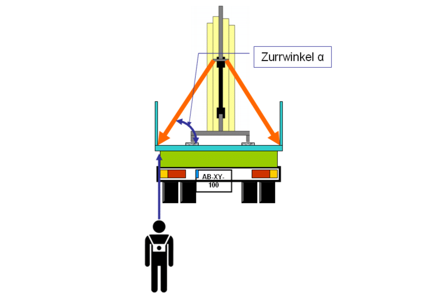
So when I look at the angles, I have to stand in the right position, looking along the loading edge to which the lashing equipment is attached.
The lashing angle α is between the loading surface and the lashing equipment.

If the same lashing equipment is considered transverse to the direction of travel, the angle must be 90º to the edge of the loading area so that the lashing angle α can have its maximum effect.
If this is not the case, the lashing angle β automatically results, which further reduces the effective securing force.

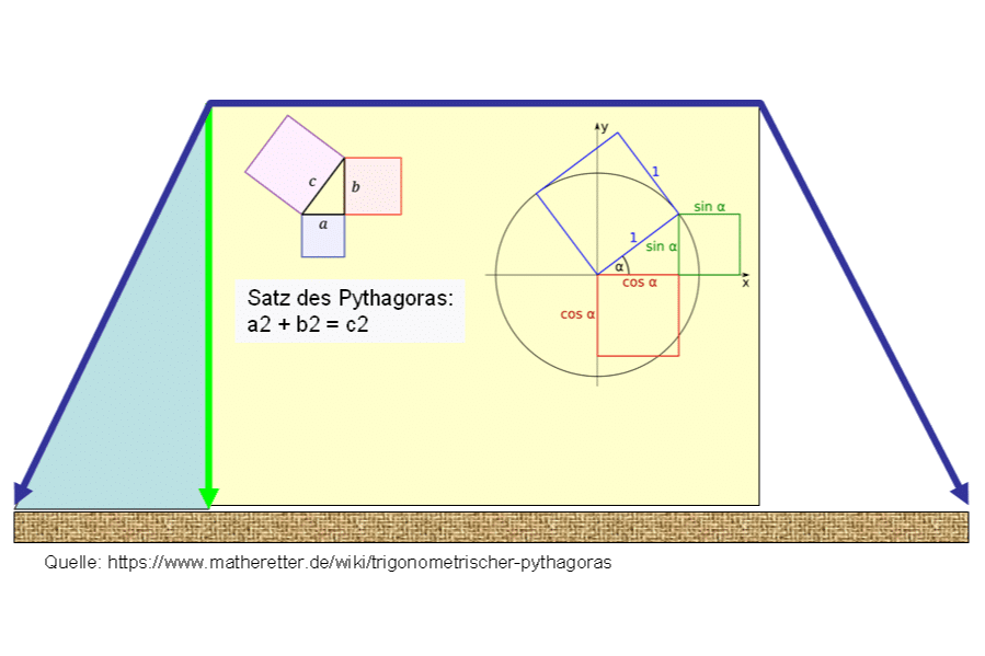
To understand the connections, we have to go back to our school days and remember the Pythagorean theorem and the right-angled triangle.
It is precisely these functions that are important for tie-down lashing (including direct lashing).

When lashing down, it depends on the amount of force that is applied vertically to the loading surface. With a lashing angle α of 90º, the green and blue lines would be the same length.
This means that the pre-tensioning force acts 1:1 on the loading surface and thus increases the frictional force between the load and the loading surface by 100%.

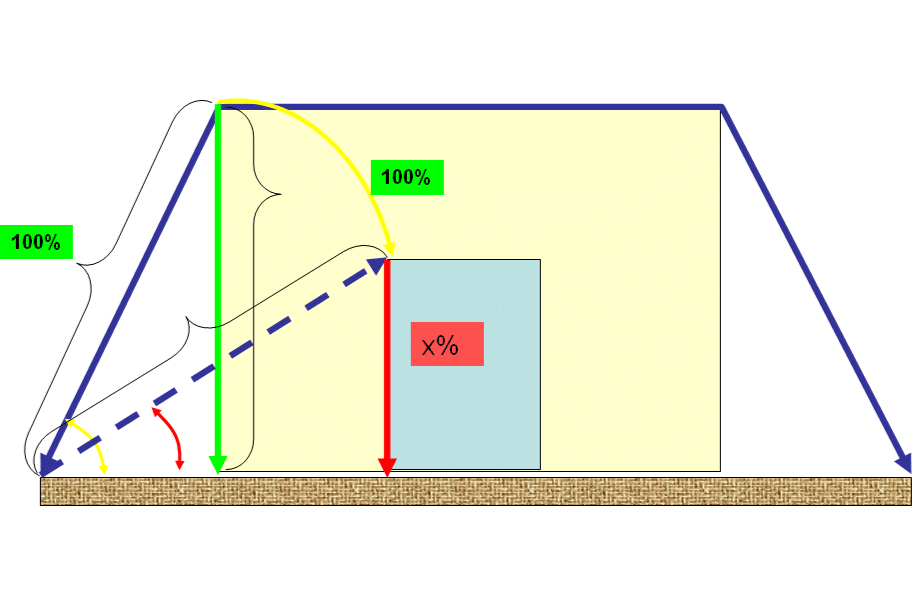
If, as is often the case, we now have a load that is narrower than the loading area, the lashing angle α automatically becomes smaller than 90º.
This leads to the effect that the vertical force component is greatly reduced, depending on the angle.
If it falls below a certain size, the tie-down lashing method is no longer sufficiently effective.
The following diagram shows the relationship between angle, preload force and frictional force. A long-lever tension ratchet with an STF=500daN is used. That should be the standard.
The second column shows the lashing angle and the third the corresponding sine.
You can also imagine the sine as a percentage. At a lashing angle of 85º, 99.6%, i.e. 498 daN, of the pre-tensioning force is still retained.
Column 5 shows the actual securing force as a function of the coefficient of friction. If the loading area is swept clean, the value µ=0.3 can generally be assumed.
If you were to position a anti-slip mat correctly on this broom-clean loading area, the values in column 6 would apply.

The green fields in the table show the values for which the tie-down lashing method can be used without risk. For the fields highlighted in yellow, the angle must be taken into account, i.e. included in the calculation. The red fields show the area in which the tie-down lashing method should be abandoned and another securing method considered.
In general, the total weight of the load must also be taken into account. A standard semi-trailer with a length of 13.60 m has at least 11 lashing eyes (in accordance with EN 12640), often 13. This means that only a maximum of 11-13 straps can be attached, which automatically limits the maximum securing force. With a lashing angle of 85º, this would be a securing force of 1,628 daN without anti-slip mats and 3,245 daN with mats. So that’s not very much.
These considerations show that although the tie-down lashing method is the most commonly used, it is also extremely problematic.

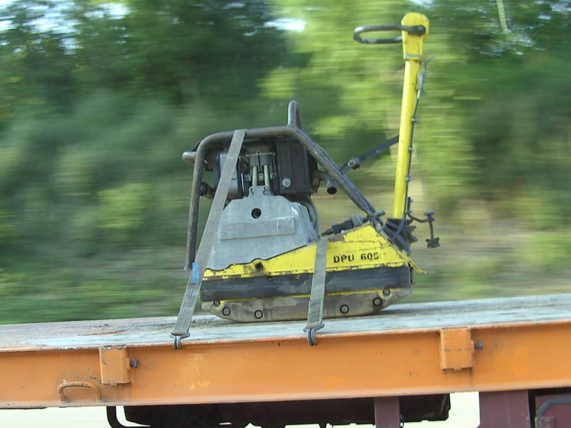
An example from practice. When securing this vibratory plate, there was almost no room for error. Unfavorable lashing angle, dirty loading area, no anti-slip mats and inadmissible attachment points.
This article is intended to encourage the reader to review and critically evaluate the standard practice for securing loads in their area.
If necessary or uncertain, the securing method should be changed if necessary.
Yours, Sigurd Ehringer
<< Previous post
Episode 26: MSL and LC – abbreviation with meaning
Next article >>
Episode 28: Prestressing force (STF) and lashing capacity (LC)

Sigurd Ehringer
✔ VDI-zertifizierter Ausbilder für Ladungssicherung ✔ Fachbuch-Autor ✔ 8 Jahre Projektmanager ✔ 12 Jahre bei der Bundeswehr (Kompaniechef) ✔ 20 Jahre Vertriebserfahrung ✔ seit 1996 Berater/Ausbilder in der Logistik ✔ 44 Jahre Ausbilder/Trainer in verschiedenen Bereichen —> In einer Reihe von Fachbeiträgen aus der Praxis, zu Themen rund um den Container und LKW, erhalten Sie Profiwissen aus erster Hand. Wie sichert man Ladung korrekt und was sind die Grundlagen der Ladungssicherung? Erarbeitet und vorgestellt werden sie von Sigurd Ehringer, Inhaber von SE-LogCon.
Rothschenk assortment
Our customer center has only one goal: to turn your problems into solutions. Whether standard stowage cushions, bestsellers or load securing personally tailored to your needs -. we accompany you consistently from A as in field service to Z as in certification. That is our promise to you, as a leader in our industry.
We attach great importance to professional cargo securing. That is why we have our own production, which ensures reliable operation through modern manufacturing technologies and strict quality control. Thus, we offer our customers a comprehensive and high-quality range of services in the field of transport logistics.
DIN ISO 9001:2015, EMAS and Ecovadis are not foreign words to you? Then it's time to work with the best.
You don't take any risks with us - we have been awarded the Platinum Medal on the EcoVadis sustainability rating platform.
As a load securement company, we are proud to have several certifications that validate our sustainability efforts and our commitment to environmental protection and social responsibility. For you as a purchaser, this means that we demand and promote the implementation of high environmental and social standards both within the company and along the supply chain.
G&H GmbH Rothschenk
Industriestrasse 5 & 7-10
97239 Aub
Phone: +49 9335 97 15 – 79
Fax: +49 9335 97 15 – 15
E-mail: info@rothschenk.de
Collection/delivery
Mon – Fri: 8:00 – 15:00
Office hours
Mon – Thu: 8:00 – 17:00
Fri: 8:00 – 13:00
G&H GmbH Rothschenk
Industriestrasse 5 & 7-10
97239 Aub
Phone: +49 9335 97 15 – 0
Fax: +49 9335 97 15 – 15
E-mail: info@rothschenk.de
Collection/delivery
Mon – Fri: 8:00 – 15:00
Office hours
Mon – Thu: 8:00 – 17:00
Fri: 8:00 – 13:00
You are currently viewing a placeholder content from Google Maps. To access the actual content, click the button below. Please note that doing so will share data with third-party providers.
More Information