Now 10% off all Ergolash lashing straps save now! Voucher code: ergo10 | Valid until 31.05.2025
EN-12142 “Securing loads on road vehicles – Superstructures on commercial vehicles – Minimum requirements” has been in existence since 2007 and vehicle superstructures have become better and better over the years.
Almost only bodies that correspond to the Code XL profile are produced. In relation to the front wall, this means a minimum load capacity of 50% of the technical payload.

The increased use of Code XL superstructures is a good thing in itself. In practice, however, mistakes are repeatedly made because the people involved are often unaware of the boundary conditions that need to be observed to ensure that the strength of the structure can be utilized while preventing overloading.
In today’s edition of the LaSi blog, I would like to take a closer look at the bulkhead and describe a few common faults and their remedies.
Two construction methods have been developed for end walls. One consists of a full-surface steel end wall and the other of transverse aluminum blanks. Both are connected to the corner posts.
The bulkhead is the component of a vehicle that has to absorb the most forces in the event of an emergency, namely emergency braking with a deceleration of 0.8 g. If you take the time to read EN-12142 carefully, you will see that it is a test standard for vehicle bodies. In the first step, it has nothing to do with load securing.
Only at the very end does the 2016 edition state that the proven forces can also be used for load securing. This statement puts what most people have already done on a legally secure footing.

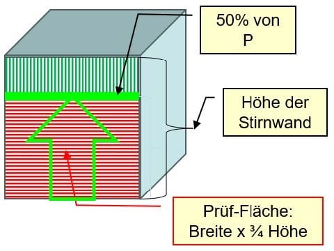
The test standard states that the end wall must be tested across its entire width. The minimum strength specifications (50% of the technical working load [P]) must be achieved in ¾ of the end wall height.
This is precisely where mistakes are often made, because the load does not cover the entire width of the end wall or does not have a positive fit to the end wall. So what are the causes?
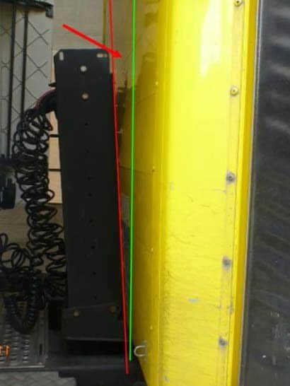
Some body manufacturers design the front wall in such a way that it forms a flat U-profile. The picture on the left shows that the first row of pallets partially disappears behind it.
When loading from the side, the loader must ensure that he pushes the pallets behind the profile so that the gap is closed. If the forklift truck has a side lift, this is an advantage for the loading process because it makes it easier to stow the load tightly against the front wall.
The result could look like the picture on the right. When braking, the load deformed the bulkhead together with the holder for the connections. Recognizable by the gap between the bracket, which is permanently deformed, and the front wall.


Another source of error is the problem of load distribution. The overall center of gravity of the load must be shifted to the rear, for example, so as not to overload the drive axle.
In the following example, the empty palettes can only be seen symbolically as placeholders. They must of course be packed in real time.

The solution to the problem is often to place the pallets one behind the other.
As a result, the force exerted by the load during emergency braking is transferred to too small an area.
The end wall is massively overloaded and can be damaged.

A better solution would be to place two pallets across the front wall so that the entire width is used.
Then continue to stow the pallets individually in a form-fit manner.
How many have to be stowed individually depends on the respective load or pallet weight.
Another solution is the use of bumper pads as gap fillers or spacers. However, this is more of an approach for regularly recurring situations.
But then it is an elegant, fast and efficient solution. It looks as follows:
The first row of loaders is positioned directly and positively against the front wall in order to transmit the power across the entire width.
An appropriately dimensioned 3Ddunnage bag is then inserted and the next row of loaders is stowed flush and flush against it.
After the second loading row, another dunnage bag can be positioned and then the rest of the load.
How the overall center of gravity changes must be checked on the basis of the load distribution plan.
In any case, it is important that the force is transmitted evenly across the width of the end wall.


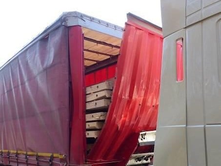
The following two pictures show an impression of incorrect end wall loading:
An A-frame was used as a spacer. When braking, the load transferred the force to the bulkhead via the too small surface of the A-frame. It was overloaded and gave way. The aluminum blanks were simply pressed through.

The load was stowed in such a way that it did not cover the entire width of the bulkhead.
The steel bulkhead was pushed out during braking. The connection between the end wall and the corner posts has yielded to this force.
Source: March 2016 – Transport Informations Service (tis-gdv.de)
Interested readers can find more pictures and details of this situation here.
It is therefore important that those responsible in a company where such situations could arise deal with the matter.
Typical loads that can cause such damage are, for example: Mesh boxes, octabins, big bags, IBCs or full pallets with beverage crates.
Yours, Sigurd Ehringer
<< Previous article
Episode 35: Bay lashing or sling lashing – application and possible uses

Sigurd Ehringer
✔ VDI-zertifizierter Ausbilder für Ladungssicherung ✔ Fachbuch-Autor ✔ 8 Jahre Projektmanager ✔ 12 Jahre bei der Bundeswehr (Kompaniechef) ✔ 20 Jahre Vertriebserfahrung ✔ seit 1996 Berater/Ausbilder in der Logistik ✔ 44 Jahre Ausbilder/Trainer in verschiedenen Bereichen —> In einer Reihe von Fachbeiträgen aus der Praxis, zu Themen rund um den Container und LKW, erhalten Sie Profiwissen aus erster Hand. Wie sichert man Ladung korrekt und was sind die Grundlagen der Ladungssicherung? Erarbeitet und vorgestellt werden sie von Sigurd Ehringer, Inhaber von SE-LogCon.
Rothschenk assortment
Our customer center has only one goal: to turn your problems into solutions. Whether standard stowage cushions, bestsellers or load securing personally tailored to your needs -. we accompany you consistently from A as in field service to Z as in certification. That is our promise to you, as a leader in our industry.
We attach great importance to professional cargo securing. That is why we have our own production, which ensures reliable operation through modern manufacturing technologies and strict quality control. Thus, we offer our customers a comprehensive and high-quality range of services in the field of transport logistics.
DIN ISO 9001:2015, EMAS and Ecovadis are not foreign words to you? Then it's time to work with the best.
You don't take any risks with us - we have been awarded the Platinum Medal on the EcoVadis sustainability rating platform.
As a load securement company, we are proud to have several certifications that validate our sustainability efforts and our commitment to environmental protection and social responsibility. For you as a purchaser, this means that we demand and promote the implementation of high environmental and social standards both within the company and along the supply chain.
You are currently viewing a placeholder content from Google Maps. To access the actual content, click the button below. Please note that doing so will share data with third-party providers.
More Information